
1. Introduction
In 1990, the ‘Electrical Engineering and Information Technology Department’ established under the leadership of Prof. Dr. D. Fasold a new Laboratory for Satellite Communications which is mainly involved in high performance antenna testing and design.
In 1995, a first indoor far-field test range was replaced by a larger, self designed anechoic chamber, equipped with a novel type of test range called ‘Compensated Compact Test Range (CCR)’, which was designed and installed for the first time by MBB, now Airbus Defence & Space, Ottobrunn in 1988 [1]. The smaller model 20/17 with a test zone of 1,3 x 1,3 x 1,5 m was established in the Laboratory as shown in Fig. 1. It is one of the fourteen world wide existing facilities of this type. In comparison to near field test facilities, measurements in compact ranges can be carried out in real time. The applicable frequency range is (1,0) 3,5 to 400 GHz and beyond.
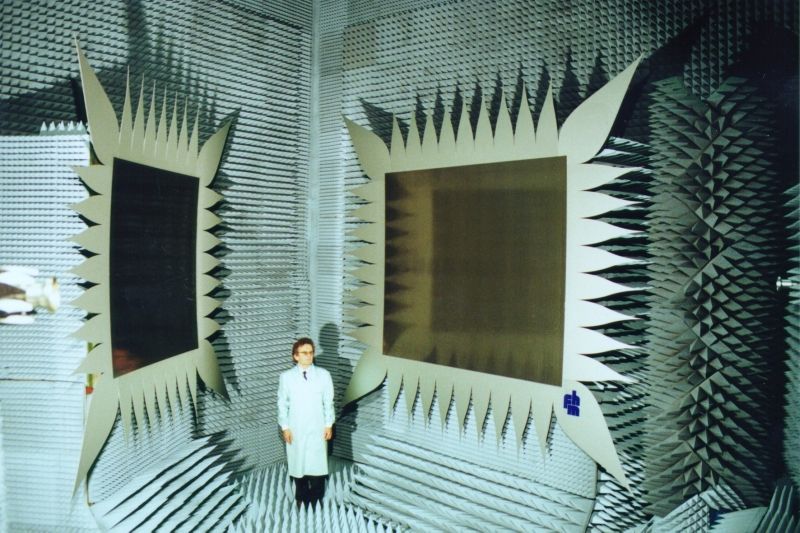
Fig. 1: Compensated Compact Test Range at the Munich University of Applied Sciences
2. Description of Facility
The CCR is based on the principle that a spherical wave coming from a source antenna is converted into a plane wave by means of two focusing, high precision reflectors (acc. <= 25 µm RMS) arranged in an optimized geometry in a closed anechoic chamber. Due to the concept of two compensated doubly curved reflectors, no system introduced cross polarization occurs in the test zone for both linear and circular polarization. The improved amplitude and phase uniformity in the test zone compared to single reflector systems is obtained by the large equivalent focal length of 37 m of the double reflector system.
The maximum amplitude and phase ripple within the test zone amounts to a figure of better than ± 0,5 dB for amplitude and ±5 degr. for phase. The comparable phase figure in standard far-field ranges comes up to 22,5 degr..
Fig. 2 shows the ground plane of the range. A very compact design was chosen, which resulted in a distance between the center of the main reflector and the device under test (DUT) of appr. 4,5 m. The reflector system is rotated by appr. 23 degr., which significantly reduces the ‘in phase’ reflection of the plane wave at the backwall behind the DUT. This improves the measurement performance for bistatic and monostatic RCS measurements.
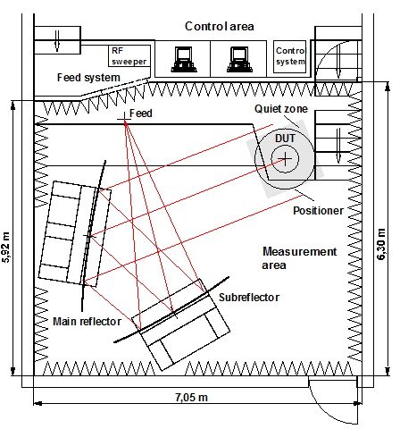
Fig. 2: Top view of CCR
The test chamber with the dimension of 7m x 6m x 6m is completely covered with pyramidal absorbers of 10 to 30 cm height. High performance feeds with low cross-polarization of ‑ 50 dB are available from 1,7 GHz up to 110 GHz. A six axes computer controlled positioning system allows precision measurements of appr. ± 0,01 degr. accuracy. The control and measurement software is menu driven and allows flexible control of all axes via IEEE-Bus. In the autoscan mode data collection by phase and amplitude is automatically performed on a sphere around the DUT. With the aid of post processing routines the recorded data can be corrected and prepared for 2D and 3D presentations.
3. Developments and Improvements
For improvement of the measurement accuracy in compact ranges specific investigations and developments had been carried out. Most of the results have been obtained within a long term study for INTELSAT, Washington [4].
- Theoretical and experimental analyses of serrated edge structures of the range reflectors.
- Development of a fast hardgating system to suppress distorting fields in the test zone, i.e. the direct radiation of the feed and the diffracted fields from the reflector edges [2].
- Development and test of a SERAP structure (Serration Radiation Protection) for effective suppression of distorting fields according to triple diffraction/reflection effects [3].
- Development of a high precision polar plane wave scanner with a laser controlled error correction system achieving an accuracy of < 40 µm RMS (see Fig. 3).
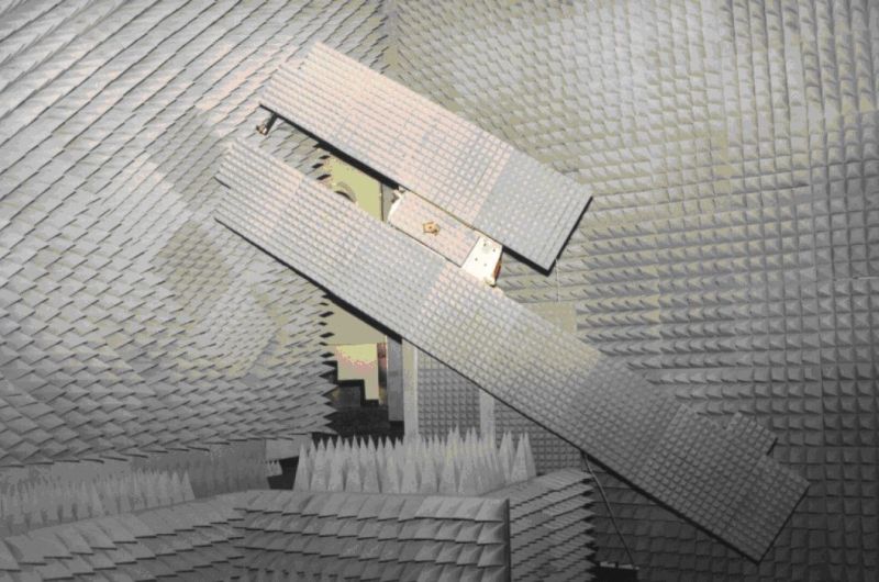
Fig. 3: Polar plane wave scanner, scan diam. 2,6 m
With the above mentioned improvements the highest standard of measurement accuracy could be achieved for co- and cross-polar radiation pattern and gain measurements. Fig. 4 shows the co-polar radiation pattern of a high gain offset reflector antenna (gain = 37,5 dBi) measured with and without hardgating.
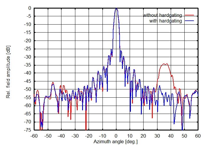
Fig. 4: Measured radiation pattern of high gain offset reflector antenna at 12 GHz
The quality of the plane wave field in the test zone measured with the polar plane wave scanner at 13 GHz is shown in Fig. 5.
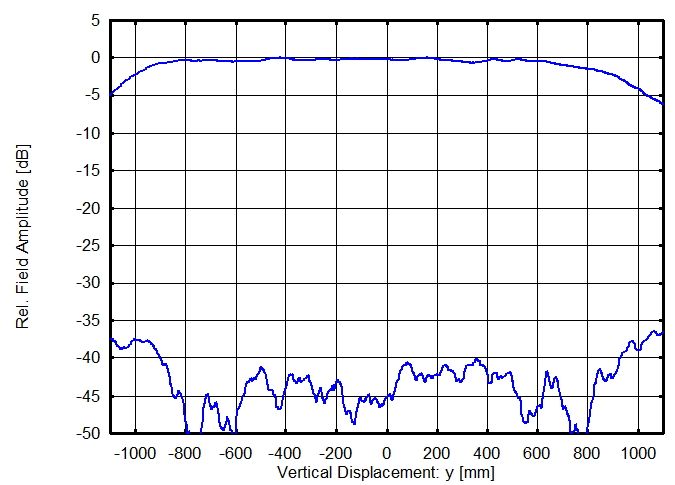
Fig. 5: Measured quality of test zone at 13 GHz for co- and cross-polarization
3D measurements of a scaled satellite model are shown in Fig. 6 for circular polarization.
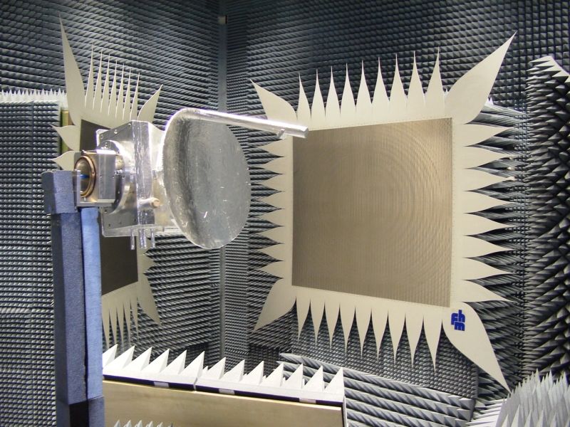
Fig. 6: Test of Scaled Satellite Model at 14.5 GHz
4. Activities and Use of Facility
The CCR test facility and the laboratory for satellite communications is used for the following areas of applications:
- Laboratory exercises for students as a supplement to the lectures on ‘Communication Satellites and Space Antennas’.
- Basis to diploma, master and PhD theses.
- Research and development activities in cooperation with the industry in the field of antenna measurements, facility design and design of horn and reflector antennas.
- Services for external customers for high precision antenna measurements in the frequency range of 1,0 GHz to 110 (400) GHz.
5. References
[1]E. Dudok, D.Fasold, H.-J. Steiner: ‘Development of an Optimized Compact Range’, 11th ESTEC Antenna Workshop on Antenna Measurements, Gothenburg, Sweden, 1988
[2]J. Hartmann, D. Fasold: ‘A Flexible Hardgating System as a Diagnostic Tool in Single and Double Reflector Compact Ranges’, Proc. of AMTA 98,Montreal, Canada, 1998
[3]J. Hartmann, D. Fasold: ‘Analysis and Performance Verification of Advanced Compensated Compact Ranges’, Proc. of 29th European Microwave Conf. 99, Munich, Germany, 1999
[4]J. Hartmann, J. Habersack, H.-J. Steiner, D. Fasold, R. Kis: ‘Development of Highly Accurate Measurement Techniques for State-of-the-Art Antenna Test Facilities, Proc. of AMTA 2002, Cleveland, USA, 2002